In digital circuit experiments, several instruments and instruments are needed to observe experimental phenomena and results. Commonly used electronic measuring instruments include multimeters, logic pens, ordinary oscilloscopes, storage oscilloscopes, and logic analyzers. The use of multimeters and logic pens is relatively simple, and logic analyzers and storage oscilloscopes are currently not widely used in digital circuit teaching experiments. An oscilloscope is a very widely used instrument that is relatively complex to use. This chapter introduces the principle and usage of the oscilloscope from the perspective of use. 1 How the oscilloscope works
An oscilloscope is an electronic measuring instrument that uses the characteristics of an electronic oscilloscope to convert an alternating electric signal that cannot be directly observed by the human eye into an image and display it on a fluorescent screen for measurement. It is an important instrument for observing the experimental phenomena of digital circuits, analyzing the problems in experiments, and measuring the results of experiments. The oscilloscope consists of an oscilloscope and power system, a synchronization system, an X-axis deflection system, a Y-axis deflection system, a delay scanning system, and a standard signal source.
Oscilloscope
Cathode ray tube (CRT) is called the oscilloscope tube and is the core of the oscilloscope. It converts electrical signals into optical signals. As shown in Figure 1, the electron gun, deflection yoke and phosphor screen are sealed in a vacuum glass envelope to form a complete oscilloscope tube.
Figure 1 shows the internal structure of the oscillating tube and the power supply
Fluorescent screen
The current oscilloscope screen is usually a rectangular plane, and a phosphor film is deposited on the inner surface to form a fluorescent film. An evaporation aluminum film is often added to the fluorescent film. High-speed electrons pass through the aluminum film and strike the phosphor to illuminate to form a bright spot. The aluminum film has an internal reflection effect, which is beneficial to increase the brightness of the bright spot. The aluminum film also has other effects such as heat dissipation.
When the electrons stop bombardment, the bright spots cannot disappear immediately and remain for a while. The time elapsed after the brightness of the bright spot drops to 10% of the original value is called "afterglow time". The afterglow time is shorter than 10μs for extremely short afterglow, 10μs-1ms for short afterglow, 1ms-0.1s for medium afterglow, 0.1s-1s for long afterglow, and greater than 1s for extremely long afterglow. The general oscilloscope is equipped with a medium afterglow oscilloscope, the high frequency oscilloscope uses a short afterglow,
Due to the different phosphorescent materials used, different colors of light can be emitted on the screen. Generally, oscilloscopes use green light-emitting oscilloscopes to protect people's eyes.
Electron gun and focus
The electron gun is composed of a filament (F), a cathode (K), a grid (G1), a front accelerating pole (G2) (or a second grid), a first anode (A1), and a second anode (A2). Its role is to emit electrons and form a very fine high-speed electron beam. The filament energizes the cathode and the cathode emits electrons by heat. The grid is a metal cylinder with a small hole at the top and is placed outside the cathode. Since the gate potential is lower than that of the cathode, it controls the electrons emitted from the cathode. Generally, only a small amount of electrons with a large initial velocity can pass through the gate aperture and rush to the phosphor screen under the action of the anode voltage. Electrons with a small initial velocity still return to the cathode. If the gate potential is too low, all of the electrons return to the cathode, ie the tube is turned off. Adjusting the W1 potentiometer in the circuit can change the gate potential and control the electron flux density that is directed to the screen to achieve the brightness of the bright spot. The first anode, the second anode, and the front accelerating pole are all three metal cylinders on the same axis as the cathode. The front accelerating pole G2 is connected to A2, and the applied potential is higher than A1. The positive potential of G2 accelerates the cathode electrons toward the phosphor screen.
The electron beam passes through the focusing process twice from the cathode to the phosphor screen. The first focus is done by K, G1, G2, and K, K, G1, G2 are called the first electron lens of the oscilloscope. The second focus occurs in the G2, A1, and A2 regions, and the potential of the second anode A2 is adjusted so that the electron beam can just converge on the phosphor screen, which is the second focus. The voltage on A1 is called the focus voltage, and A1 is called the focus pole. Sometimes adjusting the A1 voltage still does not satisfy the good focus. The voltage of the second anode A2 needs to be fine-tuned. A2 is also called the auxiliary focus pole.
Deflection system
The deflection yoke controls the direction of the electron beam so that the spot on the screen draws the waveform of the signal under test as a function of the applied signal. In Fig. 8.1, two pairs of mutually perpendicular deflection plates, Y1, Y2 and X1, X2, constitute a deflection yoke. The Y-axis deflection plate is in front and the X-axis deflection plate is behind, so the Y-axis sensitivity is high (the measured signal is processed and added to the Y-axis). The two pairs of deflection plates are respectively applied with voltages to form an electric field between the two pairs of deflection plates, respectively controlling the deflection of the electron beams in the vertical direction and the horizontal direction.
Oscilloscope power supply
In order for the oscilloscope to work properly, there are certain requirements for the power supply. It is prescribed that the potential between the second anode and the deflector is similar, and the average potential of the deflector is zero or close to zero. The cathode must operate at a negative potential. The gate G1 is at a negative potential (-30V~-100V) with respect to the cathode, and is adjustable to achieve luminance adjustment. The first anode is a positive potential (about +100V~+600V) and should also be adjustable for use as a focus adjustment. The second anode is connected to the front accelerating pole, and has a positive high voltage (about +1000 V) to the cathode, and an adjustable range of ±50 V with respect to the ground potential. Since the current of each electrode of the oscilloscope tube is small, it can be supplied by a common high voltage via a resistor divider.
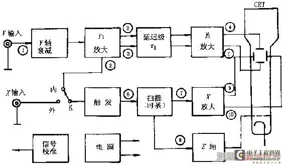
Figure 2 oscilloscope basic composition block diagram
The signal 1 to be measured is connected to the "Y" input terminal, and is appropriately attenuated by the Y-axis attenuator and then sent to the Y1 amplifier (preamplifier) ​​to push-pull the output signals 2 and 3. The delay stage is delayed by Г1 time to the Y2 amplifier. Amplification produces a sufficiently large signal 4 and 5 to be applied to the Y-axis deflection plate of the oscilloscope. In order to display a complete stable waveform on the screen, the signal D of the Y-axis is introduced into the trigger circuit of the X-axis system, and a trigger pulse 6 is generated at a certain level of the positive (or negative) polarity of the incoming signal to start. A sawtooth scanning circuit (time base generator) generates a scanning voltage 7. Since there is a time delay Г2 from the trigger to the start of the scan, to ensure that the X-axis begins to scan before the Y-axis signal reaches the screen, the delay time Г1 of the Y-axis should be slightly larger than the delay time Г2 of the X-axis. The scan voltage 7 is amplified by an X-axis amplifier to produce push-pull outputs 9 and 10 which are applied to the X-axis deflection plate of the oscilloscope. The z-axis system is used to amplify the sweep voltage forward and become a forward rectangular wave that is sent to the oscilloscope gate. This causes the waveform displayed in the scan forward to have a certain fixed luminance, while the scanning backhaul is used to erase the trace.
The above is the basic working principle of the oscilloscope. The dual trace display uses the electronic switch to display two different measured signals input to the Y axis on the screen. Due to the visual persistence of the human eye, when the switching frequency is high to a certain extent, two stable and clear signal waveforms are seen.
There is often an accurate and stable square wave signal generator in the oscilloscope for calibration oscilloscopes.
2 oscilloscope use
This section describes how to use the oscilloscope. There are many types and models of oscilloscopes, and their functions are different. Most of the digital circuit experiments used are 20MHz or 40MHz dual-track oscilloscopes. These oscilloscope usages are similar. This section does not address a certain model of oscilloscope, but only conceptually introduces the common functions of the oscilloscope in digital circuit experiments.
Fluorescent screen
The screen is the display portion of the oscilloscope. There are multiple tick marks in the horizontal and vertical directions on the screen to indicate the relationship between the voltage and time of the signal waveform. The horizontal direction indicates time and the vertical direction indicates voltage. The horizontal direction is divided into 10 grids, the vertical direction is divided into 8 grids, and each grid is divided into 5 divisions. The vertical direction is marked with 0%, 10%, 90%, 100%, etc. The horizontal direction is marked with 10%, 90% mark, and is used for measuring DC level, AC signal amplitude, delay time and other parameters. The voltage value and the time value can be obtained by multiplying the number of cells occupied by the signal under test by an appropriate proportional constant (V/DIV, TIME/DIV).
Oscilloscope and power system
1. Power (Power)
The oscilloscope main power switch. When this switch is pressed, the power indicator lights up to indicate that the power is on.
2. Intensity
Rotate this knob to change the brightness of the spot and scan line. It can be smaller when observing low frequency signals, and larger when high frequency signals are used.
Generally should not be too bright to protect the screen.
3. Focus
The focus knob adjusts the beam section size to focus the scan line to the sharpest state.
4. Ruler brightness (Illuminance)
This knob adjusts the brightness of the light behind the screen. Under normal indoor light, the lighting is darker. In an environment where there is insufficient indoor light, the lighting can be appropriately adjusted.
Vertical deflection factor and horizontal deflection factor
1. Vertical deflection factor selection (VOLTS/DIV) and fine tuning
Under the action of a unit input signal, the distance at which the spot is offset on the screen is called the offset sensitivity. This definition applies to both the X and Y axes. The reciprocal of sensitivity is called the deflection factor. The unit of vertical sensitivity is cm/V, cm/mV or DIV/mV, DIV/V, and the unit of vertical deflection factor is V/cm, mV/cm or V/DIV, mV/DIV. In fact, due to the convenience of idioms and measuring voltage readings, the deflection factor is sometimes used as sensitivity.
Each channel in the oscilloscope has a vertical deflection factor selection band switch. Generally, it is divided into 10 files from 5mV/DIV to 5V/DIV in 1, 2, and 5 ways. The value indicated by the band switch represents the voltage value of one grid in the vertical direction on the screen. For example, when the band switch is placed in the 1V/DIV mode, if the signal spot on the screen moves by one grid, it means that the input signal voltage changes by 1V.
There is often a small knob on each band switch to fine tune the vertical deflection factor for each gear. Rotate it clockwise to the end in the "calibrated" position, where the vertical deflection factor value is consistent with the value indicated by the band switch. Turn this knob counterclockwise to fine tune the vertical deflection factor. After the vertical deflection factor is fine-tuned, it will cause inconsistency with the indication value of the band switch, which should be noted. Many oscilloscopes have a vertical expansion function that increases the vertical sensitivity by several times when the fine adjustment knob is pulled out (the deflection factor is reduced by several times). For example, if the deflection factor indicated by the band switch is 1V/DIV, the vertical deflection factor is 0.2V/DIV when the x5 extended state is used.
When doing digital circuit experiments, the ratio of the vertical movement distance of the measured signal on the screen to the vertical movement distance of the +5V signal is often used to determine the voltage value of the signal under test.
2. Time base selection (TIME/DIV) and fine tuning
The use of time base selection and fine tuning is similar to vertical deflection factor selection and fine tuning. The time base selection is also realized by a band switch, and the time base is divided into several files according to 1, 2, and 5 ways. The indicated value of the band switch represents the time value at which the spot moves one square in the horizontal direction. For example, in the 1μS/DIV file, the spot moves one frame on the screen to represent the time value of 1μS.
The Fine Tune knob is used for time base calibration and fine tuning. When rotated clockwise to the calibration position, the time base value displayed on the screen matches the nominal value shown by the band switch. Turn the knob counterclockwise to fine tune the time base. The knob is pulled out and is in the scan extension state. Usually x10 expansion, that is, the horizontal sensitivity is expanded by 10 times and the time base is reduced to 1/10. For example, in the 2μS/DIV file, the time value represented by the horizontal level on the screen in the scan extended state is equal to
2μS × (1/10) = 0.2μS
The TDS test bench has 10MHz, 1MHz, 500kHz, 100kHz clock signals, generated by a quartz crystal oscillator and a frequency divider. It has high accuracy and can be used to calibrate the time base of the oscilloscope.
The oscilloscope's standard source CAL is designed to calibrate the oscilloscope's time base and vertical deflection factor. For example, the standard signal source of the COS5041 oscilloscope provides a square wave signal with VP-P=2V and f=1kHz.
The Position knob on the front panel of the oscilloscope adjusts the position of the signal waveform on the screen. Rotate the horizontal displacement knob (marked with a horizontal double-headed arrow) to move the signal waveform left and right, and rotate the vertical displacement knob (labeled with a vertical double-headed arrow) to move the signal waveform up and down.
Input channel and input coupling selection
1. Input channel selection
There are at least three options for input channels: Channel 1 (CH1), Channel 2 (CH2), and Dual Channel (DUAL). When channel 1 is selected, the oscilloscope only displays the signal for channel 1. When channel 2 is selected, the oscilloscope only displays the signal for channel 2. When dual channel is selected, the oscilloscope displays both the channel 1 signal and the channel 2 signal. When testing the signal, first connect the ground of the oscilloscope to the ground of the circuit under test. According to the selection of the input channel, the oscilloscope probe is inserted into the corresponding channel socket, the ground on the oscilloscope probe is connected with the ground of the circuit under test, and the oscilloscope probe contacts the measured point. There is a two-position switch on the oscilloscope probe. When the switch is set to the “× 1†position, the measured signal is sent to the oscilloscope without attenuation. The voltage value read from the screen is the actual voltage value of the signal. When the switch is turned to the "×10" position, the measured signal is attenuated to 1/10, and then sent to the oscilloscope. The voltage value read from the screen is multiplied by 10 to be the actual voltage value of the signal.
2. Input coupling method
There are three options for input coupling: AC (AC), Ground (GND), and DC (DC). When "Ground" is selected, the scan line shows the position of the "Oscilloscope" on the screen. DC coupling is used to determine the absolute value of the signal DC and to observe the very low frequency signal. AC coupling is used to observe AC and AC signals containing DC components. In digital circuit experiments, the "DC" mode is generally selected to observe the absolute voltage value of the signal.
trigger
The first section indicates that after the signal to be measured is input from the Y-axis, part of it is sent to the Y-axis deflection plate of the oscilloscope, and the driving spot is proportionally moved in the vertical direction on the screen; the other part is shunted to the x-axis deflection system to generate a trigger. The pulse triggers the scan generator to generate a repeated sawtooth wave voltage to be applied to the X-deflection plate of the oscilloscope tube, so that the light spot moves in the horizontal direction, and the two are combined, and the pattern drawn by the light spot on the fluorescent screen is the signal to be measured. Graphics. It can be seen that the correct trigger mode directly affects the effective operation of the oscilloscope. In order to obtain a stable and clear signal waveform on the screen, it is very important to master the basic trigger function and its operation method.
1. Trigger source (Source) selection
In order to display a stable waveform on the screen, the signal to be measured itself or a trigger signal having a certain time relationship with the signal to be measured needs to be added to the trigger circuit. The trigger source selection determines where the trigger signal is supplied. There are usually three trigger sources: internal trigger (INT), power trigger (LINE), and external trigger EXT).
The internal trigger uses the measured signal as the trigger signal, which is a trigger method that is often used. Since the trigger signal itself is part of the signal being measured, a very stable waveform can be displayed on the screen. Channel 1 or channel 2 in the dual trace oscilloscope can be selected as the trigger signal.
The power trigger uses the AC power frequency signal as a trigger signal. This method is effective when measuring signals related to the frequency of the AC power source. It is especially effective when measuring low-level AC noise of audio circuits and thyristors.
The external trigger uses the external signal as the trigger signal, and the external signal is input from the external trigger input. There should be a periodic relationship between the external trigger signal and the signal under test. Since the signal under test is not used as a trigger signal, when to start scanning is independent of the signal under test.
Correct selection of the trigger signal has a great relationship with the stability and clarity of the waveform display. For example, in the measurement of digital circuits, it may be better to select an internal trigger for a simple periodic signal, and for a signal with a complex period and a signal with a periodic relationship with it, the external trigger may be more it is good.
2. Trigger coupling (Coupling) mode selection
There are many ways to couple the trigger signal to the trigger circuit, in order to stabilize and reliably trigger the signal. Here are a few of the commonly used ones.
AC coupling is also called capacitive coupling. It is only allowed to be triggered by the AC component of the trigger signal, and the DC component of the trigger signal is blocked. This coupling is typically used when DC components are not considered to form a stable trigger. However, if the frequency of the trigger signal is less than 10 Hz, it will cause difficulty in triggering.
DC coupling (DC) does not block the DC component of the trigger signal. DC coupling is preferred when the frequency of the trigger signal is low or the duty cycle of the trigger signal is large.
When the low frequency suppression (LFR) is triggered, the trigger signal is added to the trigger circuit through the high-pass filter, and the low-frequency component of the trigger signal is suppressed. When the high-frequency rejection (HFR) is triggered, the trigger signal is added to the trigger circuit through the low-pass filter, and the trigger signal is High frequency components are suppressed. There is also a TV sync (TV) trigger for TV repair. These trigger coupling methods each have their own scope of application and need to be experienced in use.
3. Trigger level (Level) and trigger polarity (Slope)
Trigger level adjustment, also known as sync adjustment, causes the sweep to be synchronized with the signal under test. The level adjustment knob adjusts the trigger level of the trigger signal. The scan is triggered as soon as the trigger signal exceeds the trigger level set by the knob. Rotate the knob clockwise to raise the trigger level; turn the knob counterclockwise to decrease the trigger level. When the level knob is adjusted to the level lock position, the trigger level is automatically maintained within the amplitude of the trigger signal, and a level adjustment is required to generate a stable trigger. When the signal waveform is complex and the level knob cannot be used for stable triggering, use the Hold Off knob to adjust the holdoff time of the waveform (scan pause time) to synchronize the sweep with the waveform.
The polarity switch is used to select the polarity of the trigger signal. When dialed in the "+" position, the trigger is generated when the trigger signal exceeds the trigger level in the direction of signal increase. When dialed in the "-" position, the trigger is generated when the trigger signal exceeds the trigger level in the direction of signal reduction. The trigger polarity and the trigger level together determine the trigger point of the trigger signal.
Scan mode (SweepMode)
Scanning has three scanning modes: Auto, Normal, and Single.
Auto: When there is no trigger signal input, or the trigger signal frequency is lower than 50Hz, the scan is self-excited.
Normal: When there is no trigger signal input, the scan is in the ready state and there is no scan line. After the trigger signal arrives, the scan is triggered.
Single: A single button is similar to a reset switch. In the single scan mode, the scan circuit is reset when the button is pressed, and the Ready light is on. A scan is generated after the trigger signal arrives. After the single scan is completed, the ready light is off. A single scan is used to observe aperiodic signals or a single transient signal, often requiring a picture of the waveform.
The basic functions and operations of the oscilloscope are described above. The oscilloscope also has some more complex functions, such as delayed sweep, trigger delay, XY mode, etc., which are not introduced here. Getting started with an oscilloscope is easy, and true proficiency is mastered in the application. It is worth pointing out that although the oscilloscope has many functions, it is better to use other instruments and instruments in many cases. For example, in a digital circuit experiment, it is much simpler to use a logic pen to determine whether a single pulse with a narrow pulse width occurs. When measuring a single pulse width, it is better to use a logic analyzer.
Galavnized ground anchors are simple piles used for fixing pull lines or temporary fixation during construction. They are composed of one or more spiral bearing plates attached to the central axis. When in use, the ground anchors are rotated into the ground by rotating the ground anchors. In the following, the tensile force between the ground anchor spiral blade and the soil layer is used to achieve a fixed effect.
Spiral ground anchors are widely used in the construction of large poles and towers because of their large torque, short installation period, and stability of different soils.
Screw ground anchor application
Install transmission towers in the field
In long-distance power transmission lines, spiral ground anchors can be used to fix the bottom of high-voltage power transmission towers in environments with difficult transportation, high water levels, swamps, soft foundations, etc., and can cope with harsh outdoor environments and soils such as sand and gravel. Tower.
Installation of communication towers and power towers
Spiral ground anchors are suitable for the stabilization of the bottom of large communication towers and power towers due to their multi-angle structural torque and tensile force, with a tensile force of 80 kilolbs. The tower foot/iron column is fixed on a steel support composed of multiple spiral ground anchors or on a platform where multiple spiral ground anchors are combined together and poured into concrete, and the overall tower body is stable.
Spiral Ground Anchor VS Concrete Pouring Spiral Ground Anchor
-Features-
(1) Convenient installation, small storage area, and reduced transportation cost
(2) Pull or fix the iron tower and iron column
(3) Support iron towers and iron pillars can be tilted forward or at a small angle
(4) Tension and grip
Galvanized Ground Anchor,Screw Foundation Anchors,Galvanised Ground Anchor,Galvanized Auger Ground Anchors
Shijiazhuang Qiancen Industry Co.,ltd , https://www.yuyilang.com