Method for maintaining tension during coating

BAIDU_CLB_fillSlot("858283");
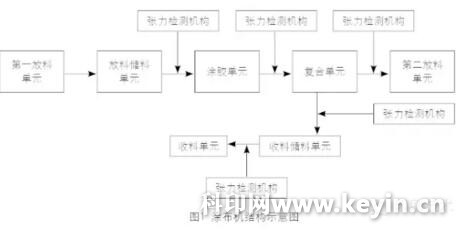
package The coating coater is mainly composed of a discharge unit, a storage unit, a coating unit, a composite unit, and a receiving unit (as shown in FIG. 1). The tension control system comprises a discharge unit, a discharge storage rack, a glue application unit, a receiving storage rack and a receiving portion. Taking the Y299D high-end coating machine in the northwest of Shaanxi as an example, the tension detection and control system of the coating machine is briefly analyzed, and the method of maintaining the tension stability during the coating process is introduced.
1. Coating machine tension detection

The coater detects the tension by means of a pendulum roller and a potentiometer, and the pendulum roller and the potentiometer are connected by gears.

Set each end of the potentiometer to P+, U, P-, PG.

Voltage value: +10V between P+ and PG, and -10V between P- and PG.

When the tension setting value = tension feedback value, the voltage between U and PG is 0V;

When the tension value changes, that is, the swing roller oscillates, the voltage between U and PG changes, thereby detecting the tension and effectively controlling the tension stability.

2. Tension control of the discharge unit

The coater is generally provided with two discharge units.

(1) The first discharge unit in Y299D is passive discharge. The unit is very mature and the tension is always stable.

(2) The second discharge unit is an active discharge. During the discharging process, the unwinding roll diameter is continuously reduced, and the discharge swing roller continuously controls the tension through the PLC and the PID controller.

The PLC controller can calculate the unwinding roll diameter, control the corresponding motor to continuously accelerate to keep the tension stable; the PID controller calculates the fine adjustment of the discharge motor speed when the offset of the discharge swing roller position, to ensure the tension is stable.

3. Tension control of the material storage rack and discharging process

The material storage rack can realize zero-speed material feeding during discharging. Before the equipment is started, the state of the material storage rack should be checked to ensure that the material storage rack is filled with the substrate and ready for discharging.

When the discharging unit needs to refuel, press the receiving button, the discharging storage rack motor accelerates, and the discharging traction motor decelerates. In this process, the discharge traction pendulum roller controls the discharge traction motor, and the discharge storage rack motor follows the host speed. When the speed of the discharge storage rack = the host speed, the speed of the discharge traction motor is reduced to zero. At this time, the discharge traction pendulum roller is switched from the originally controlled discharge traction motor to the control discharge storage frame motor, thereby ensuring stable discharge tension and smoothly carrying out zero-speed feeding.

After the discharge work is completed, press the material completion button, the discharge storage rack motor is decelerated, the discharge traction motor is accelerated, and the discharge traction roller starts to control the discharge traction motor. When the discharge storage rack motor speed is reduced to 0, the discharge traction motor speed = host speed.

The stocking rack begins to raise the stock at zero speed until it reaches the set speed. At this time, the speed of the discharge traction motor = the speed of the main engine + the rising speed of the discharge storage rack, and the tension of the process is stabilized.

When the stock is completed, the discharge hopper motor starts to decelerate at a constant speed until the speed is zero. The discharge traction motor decelerates and drops to the same speed as the main unit when the discharge stocker motor is lowered to zero.

4. Tension control of the paint unit

The circumference of the rubberized roller is fixed, so the speed of the rubber roller motor is the speed of the main machine plus the adjustment speed of the pendulum roller. The PID controller inside the Yaskawa H1000 inverter can meet the tension fine-tuning control between the glue unit and the composite unit.

5. Tension control of the receiving material storage rack and receiving process

The coating machine has various processes, and the pre-drive shaft is required to be in a stationary state at the time of receiving the material. Therefore, the coating machine should have a receiving and storage rack mechanism. Before the equipment is started, the position of the receiving and storage rack should be checked first, and the storage rack should be adjusted to automatically descend to the lower end of the storage mechanism at a certain speed, ready to receive the material.

When the receiving shaft needs to be refueled, press the receiving button, the receiving storage rack accelerates from zero, and at the same time, the receiving traction and the receiving current shaft are decelerated. In this process, the receiving traction pendulum roller controls the receiving traction motor, and the receiving storage rack motor follows the host speed. When the speed of the receiving storage rack motor = the host speed, the speed of the current traction of the receiving traction and the receiving material is reduced. Is 0. At this time, the receiving traction pendulum roller is switched from the originally controlled receiving traction motor to the control storage rack motor, thereby ensuring stable receiving tension. Subsequently, the receiving tool holder performs corresponding actions to complete the receiving work.

After the receiving action is completed, after the receiving boom falls, the receiving and storage rack motor decelerates, and the current axis of the receiving traction and receiving is accelerated. In this process, the receiving traction pendulum roller controls the receiving traction motor. When the speed of the receiving storage rack motor is reduced to 0, the receiving traction motor and the receiving current shaft speed = the host speed.

The receiving stock rack accelerates downward at zero speed until it accelerates to the set speed. At this time, the speed of the receiving traction motor and the current shaft of the receiving material = the speed of the main machine + the falling speed of the receiving material storage rack, so as to stabilize the tension of the composite unit to the receiving material storage rack and the receiving material storage rack to the receiving unit.

When the receiving stock rack descends to the deceleration mark, it starts to decelerate at a constant speed until the speed is zero. The current axis of the draw traction and receipt also decelerates, and when the speed of the receiving stocker is reduced to zero, the speed is reduced to the same speed as the host.

The above content is reproduced in the " Printing Technology " official WeChat (Printech1957) , authorized by the company to publish, copyright, piracy will be investigated !


Galvanized Hexagonal Wire Netting

ŸGalvanized hexagonal wire mesh is also named Chicken wire netting, made of low carbon iron wire, galvanized or hot-dip zinc plated before or after weaving. Hexagonal Wire Netting is firm in structure and has flat surface. It is extensively used in INDUSTRIAL AND AGRICULTURAL CONSTRUCTUONS AS REINFORCEMNET AND FENCING. It is also used as Fence for Poultry Cage, Fishing, Garden and Children playground, etc.

Assortments Available for galvanized hexagonal wire according to processing:

Hexagonal wire, Electro Galvanized before Weaving

Hexagonal wire, Electro Galvanized After Weaving

Hexagonal wire, Hot Dipped Galvanized before Weaving

Hexagonal wire, Hot Dipped Galvanized after Weaving

Galvanized chicken wire netting

Mesh

Min. Gal.v. G/SQ.M

Width

Wire Gauge (Diameter) BWG

Inch

mm

Tolerance (mm)

3/8"

10mm

±1.0

0.7mm - 145

0.5m - 1.0m

27, 26, 25, 24, 23

1/2"

13mm

±1.5

0.7mm - 95

0.5m - 2.0m

25, 24, 23, 22, 21

5/8"

16mm

±2.0

0.7mm - 70

0.5m - 2.0m

27, 26, 25, 24, 23, 22

3/4"

20mm

±3.0

0.7mm - 55

0.5m - 2.0m

25, 24, 23, 22, 21, 20, 19

1"

25mm

±3.0

0.9mm - 55

0.5m - 2.0m

25, 24, 23, 22, 21, 20, 19, 18

1-1/4"

31mm

±4.0

0.9mm - 40

0.5m - 2.0m

23, 22, 21, 20, 19, 18

1-1/2"

40mm

±5.0

1.0mm - 45

0.5m - 2.0m

23, 22, 21, 20, 19, 18

2"

50mm

±6.0

1.2mm - 40

0.5m - 2.0m

23, 22, 21, 20, 19, 18

2-1/2"

65mm

±7.0

1.0mm - 30

0.5m - 2.0m

21, 20, 19, 18

3"

75mm

±8.0

1.4mm - 30

0.5m - 2.0m

20, 19, 18, 17

4"

100mm

±8.0

1.6mm - 30

0.5m - 2.0m

19, 18, 17, 16

Note:
1.) The above tolerance comply with standard EN10223-2:1997;
2.) Minimum Galvanization is only for typical wire diameter as stipulated separately in the column for your reference; Also it is only for hot dipped Galvanized Netting.

Twist Type:

  • ŸMesh from 25 mm are reverse-twisted,
  • Mesh smaller than 25 mm are twisted three times.

For strengthening wire mesh purposes:

  • This wire mesh could has double edged Wires and the height
  • From 100 cm at the mesh from 25 mm are provided with an extra horizontal wire for better stability.
  • Mesh smaller than 25mm could also be made twisted five times, ensures that the product has higher resistance.
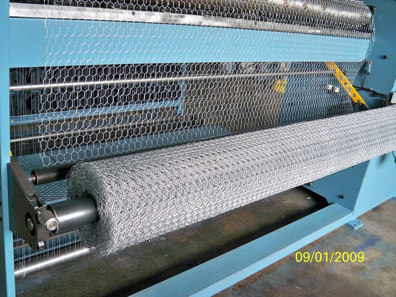
hex wire netting

Galvanized Hexagonal Wire Netting,Galvanized Chicken Wire, Hot Dipped Galvanized Hexagonal Wire Mesh,Stainless Steel Bird Wire Mesh

DINGZHOU TIAN YILONG METAL PRODUCTS CO., LTD. , https://www.wiremeshsolution.com